STANDARDS OVERVIEW
Recruitment Opportunities
BACKBONE CABLING OVERVIEW
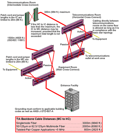
The backbone cabling system provides interconnections between telecommunications rooms, equipment rooms, main terminal space, and entrance facilities. It includes backbone cables, intermediate and main cross-connects, mechanical terminations, and patch cords or jumpers used for backbone-to-backbone cross-connections. The backbone also extends between buildings in a campus environment.
Some points specified for the backbone cabling subsystem include:
- Equipment connections to backbone cabling should be made with cable lengths of 30m (98 ft.) or less.
- The backbone cabling shall be configured in a star topology. Each horizontal cross-connect is connected directly to a main cross-connect or to an intermediate cross-connect, then to a main cross-connect.
- The backbone is limited to no more than two hierarchical levels of cross-connects (main and intermediate). No more than one cross-connect may exist between a main and a horizontal cross-connect and no more than three cross-connects may exist between any two horizontal cross-connects.
- A total maximum backbone distance of 90m (295 ft.) is specified for high bandwidth capability over copper. This distance is for uninterrupted backbone runs. (No intermediate cross-connect).
- The distance between the terminations in the entrance facility and the main cross-connect shall be documented and should be made available to the service provider.
- Recognized media may be used individually or in combination, as required by the installation. Quantity of pairs and fibres needed in individual backbone runs depends on the area served. Recognized backbone cables are:
- Multi-pair cable is allowed, provided that it satisfies the power sum crosstalk requirements.
- The proximity of backbone cabling to sources of electromagnetic interference (EMI) shall be taken into account. Cross-connects for different cable types must be located in the same facilities. Bridged taps and splitters are not allowed.
- Cross-connects for different cable types must be located in the same facilities.
- Bridged taps and splitters are not allowed.
Notes: In ISO/IEC 11801:2002, the equivalent cabling elements to the main cross-connect (MC) and intermediate cross-connect (IC) are called the campus distributor (CD) and building distributor (BD) respectively.
HORIZONTAL CABLING OVERVIEW The horizontal cabling system extends from the telecommunications outlet in the work area to the horizontal cross-connect in the telecommunications room. It includes the telecommunications outlet, an optional consolidation point or transition point connector, horizontal cable, and the mechanical terminations and patch cords (or jumpers) that comprise the horizontal cross-connect.
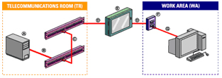
A Customer Premises Equipment
B HC Equipment Cord
C Patch cords/cross-connect jumpers used in the HC, including equipment cables/cords, should not exceed 5m (16 ft.)
D Horizontal cable 90m (295 ft.) max. total
E TP or CP (optional)
F Telecommunication's outlet/connector (TO)
G WA Equipment cord
Notes: *An allowance of 10m (33 ft.) has been provided for the combined length of patch cords/cross-connect jumpers and equipment cables/cords in the HC, including the WA equipment cords.
*In ISO/IEC 11801:2002, the equivalent cabling element to the horizontal cross-connect (HC) is called the floor distributor (FD). ISO/IEC 11801:2002 specifies a max. patch cord/cross-connect length of 5m (16.4 ft.), which does not include equipment cables/cords. An allowance is made for WA equipment cords of 5m (16 ft.)
Some points specified for the horizontal cabling subsystem include:
Recognized Horizontal Cables 4-pair 100 W unshielded twisted-pair or screened twisted-pair 2-fiber (duplex) 62.5/125µm or 50/125µm multimode optical fibre.
![]()
- Multi-unit cables are allowed, provided that they satisfy the hybrid/bundled cable requirements of TIA/EIA-568-B.2, ISO/IEC 11801:2002.
- Grounding must conform to applicable building codes, as well as ANSI-J-STD-607-A.
- A minimum of two telecommunications outlets are required for each individual work area. First outlet: 100 W twisted-pair (category 5e is recommended). Second outlet: 100 W twisted-pair category 5e, or two-fibre multimode optical fibre either 62.5/125µm or 50/125µm.
- One transition point (TP) or Consolidation Point (CP) is allowed. The term "transition point" was removed from the second edition of ISO/IEC 11801:2002. Under carpet cabling is no longer covered by that standard.
- Additional outlets may be provided. These outlets are in addition to, and may not replace, the minimum requirements of the standard.
- Bridged taps and splices are not allowed for copper-based horizontal cabling. (Splices are allowed for fibre.)
- Application specific components shall not be installed as part of the horizontal cabling. When needed, they must be placed external to the telecommunications outlet or horizontal cross-connect (e.g. splitters, baluns).
- The proximity of horizontal cabling to sources of electromagnetic interference (EMI) shall be taken into account.